What is JEDEC and How Does it Help Component Handling?
JEDEC design outlines and standards are valuable guidelines for anyone looking to leverage decades of knowledge and experience coming from the microelectronics industry. In the case of matrix trays and carriers, JEDEC Standards define common characteristics to allow commonality among equipment, hardware, and other support products. The external dimensions and features provide reference points for device location and features to allow the use of automated handling systems. JEDEC categorizes trays and carriers as “package interface” products.
Introduction
While JEDEC has focused primarily on components, the organization has created a valuable design guide for matrix trays and standardized outline drawings for trays and carriers. JEDEC compliance provides a bridge between custom components and existing industry standard equipment and processes. And in situations where full compliance is not possible, including JEDEC standard features and characteristics adds value.
What is JEDEC?
As stated on the JEDEC website, “JEDEC is the global leader in developing open standards for the microelectronics industry, with more than 3,000 volunteers representing over 350 member companies.”
Because JEDEC Standards are created by industry stakeholders, including manufacturers and users; engineers, designers, salespersons, and quality experts; all with shared and overlapping goals, adoption has far reaching impact.
JEDEC has many committees and subcommittees, each focusing on a specific topic. JC-11 is for Mechanical Standardization and its work culminates in JEDEC Publication 95. JEDEC subcommittee JC-11.5: Package Interface has been responsible for creating all matrix tray and device carrier registered outlines and standards.
JEDEC Standards
JEDEC Matrix Tray standards define many important and useful characteristics.
- Length and width
- Flatness
- Methodology for specifying tray pocket locations
- Asymmetrical end tabs for orientation
- Corner chamfer for “pin 1” orientation
- Side notches for lifting and singulating trays when stacked in tray feeders
- Side “mouse bite” notch for visual verification of alignment
- Location of temperature rating
- Location of vacuum pickup points (not possible with all tray designs)
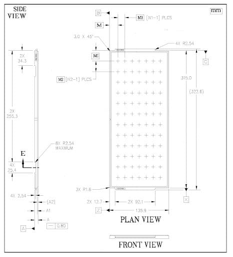
The JEDEC Matrix Tray Design Guide identifies two tray thicknesses. The “thick” profile was originally designed for through hole pin grid array packages (PGA) and the “thin” profile came later as thinner surface mount packaging became more common. In the years since, tray manufacturers have produced JEDEC outline trays with a wide range of thicknesses to accept many different component types and sizes.
JEDEC Tray Standards have become globally accepted as the preferred way to handle components that will be installed onto PCBs. Some of the most popular standards are for:
JEDEC Carrier outlines were developed to allow standardization of test and burn-in socket designs. There are carrier outlines for several sizes but all share some common elements.
- Three orientation notches to provide gross alignment and polarization for socket alignment
- Pin 1 indicators for package insertion orientation
- Where side “rails” are included, differing widths to provide polarization to extruded shipping tubes
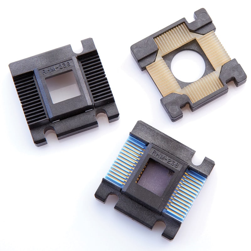
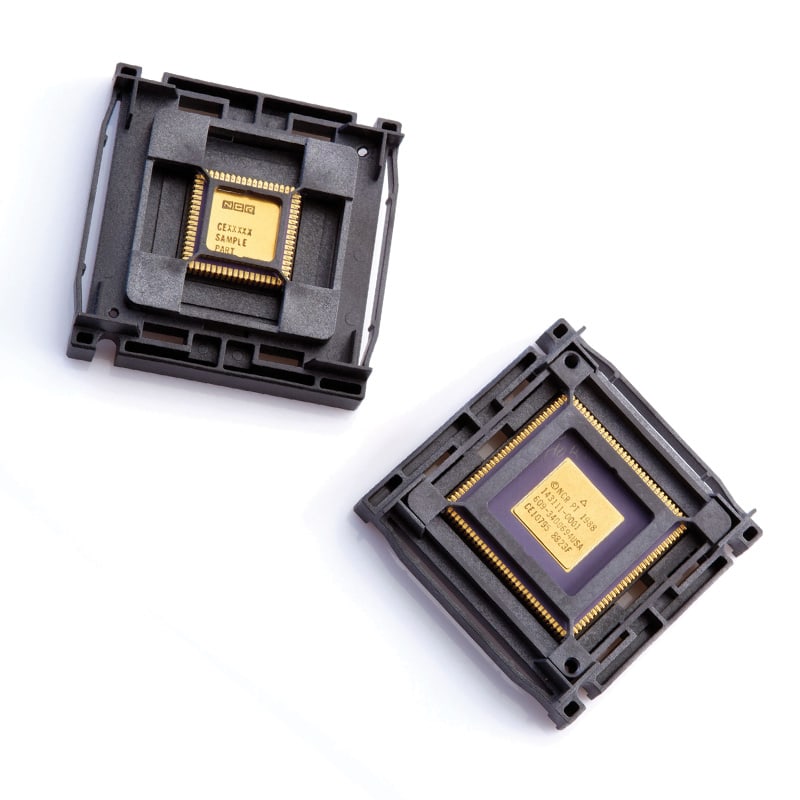
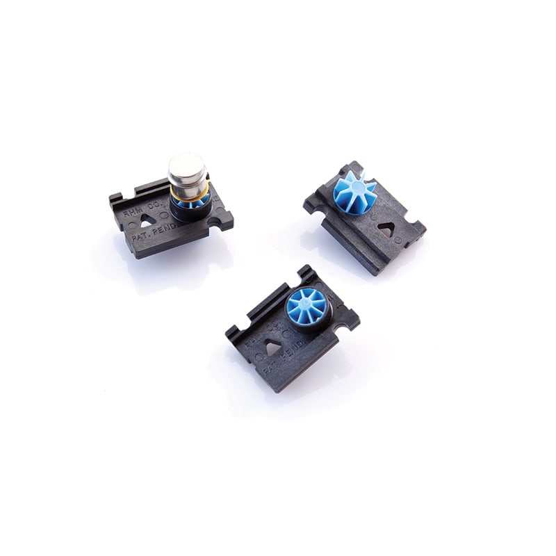
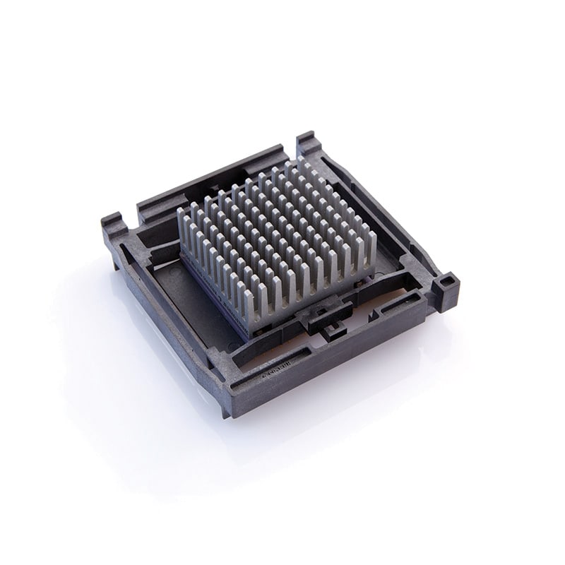
It is important to remember that the JEDEC tray and carrier standards control the external geometries but they do not dictate how components are located or supported. The interior of the trays and carriers is where the designers must be creative, finding the best way to capture a component while allowing for all the functionality required and remaining manufacturable.
How JEDEC Standards are Developed
JEDEC standards are the outcome of a process that includes input from, and consideration by a large group of stakeholders. A JEDEC committee member can sponsor a new or revised standard. The proposal includes background information and reasoning for need, along with the details of the proposed standard.
The proposed standard must be approved by vote of the committee which oversees the technology being considered. For matrix trays it is the JC-11.5: Package Interface committee. Membership in the committee is very diverse, including users, manufacturers, distributors, materials suppliers, and other interested groups.
To gain approval, the needs and desires of many must be considered and addressed. Standards may become generalized or diluted to serve the interests of such a large group. But the process increases the likelihood of widespread adoption, and therefore the value of the standard.
Benefits of JEDEC Standards
JEDEC Standards have varying impact depending on one’s role and involvement with the product. For JEDEC matrix trays here are some benefits.
- For Users – equipment availability and cost, storage efficiency, proven packaging reliability, process standardization, choice of manufacturing partners
- For Designers – framework in which the design is created, common “language” and specification template, resource library
- Manufacturers – sizes and types of equipment needed, assurances of manufacturability and acceptance, platform simplification, established quality standards
- WARNING!! Compliance with JEDEC Matrix Tray Standards offers no assurances of component compatibility or tray interchangeability.
JEDEC matrix trays are custom designed and manufactured. Many of them are not only device specific but device manufacturer specific. It’s not uncommon for two component sources’ parts to require different trays because of allowable variation in package sizing. Component footprint (for PCB layout) is more tightly controlled than packaging which varies greatly with packaging technology and material.
Off-the-shelf simply means a manufacturer has enough demand for a specific custom tray that they carry some inventory. More common is open-tooled where a custom mold will be set up and run for any order but often with a minimum quantity and/or significant setup charges.
JEDEC trays from multiple manufacturers generally should not be mixed, even when designed for the exact same device. The way the device is supported and located, and the height at which it is located within the tray’s thickness, is unique for every tray. JEDEC only defines the tray outline and recommends the pocket center locations.
Conclusion
JEDEC has established itself as a credible and effective source of guidance for many aspects of the microelectronics ecosystem. But JEDEC’s influence and the benefits of their work has extended to many other areas. Anyone with a need to move or handle components or products of similar size should look at JEDEC standardized formats to leverage the decades of experience and refinement they bring.