How to Get a JEDEC QFP Matrix Tray
Selecting the correct JEDEC matrix tray requires more than a QFP package description, lead count, or set of data sheet dimensions. This guide explains the information needed to evaluate a CQFP, PQFP, TQFP, MQFP, or other Quad Flat Pack IC package for the correct tray.
Why the Package Description Is Not Enough
Quad Flat Pack, QFP, packages are a family of semiconductor devices characterized by having terminal leads on all four sides. The leads get formed so that the devices can be surface mounted to PCBs and modules. The packages may be square or rectangular.
QFPs are often described by either their total lead count, such as a 208 QFP, or their body dimensions, such as a 28 mm MQFP or 14 mm x 20 mm CQFP.
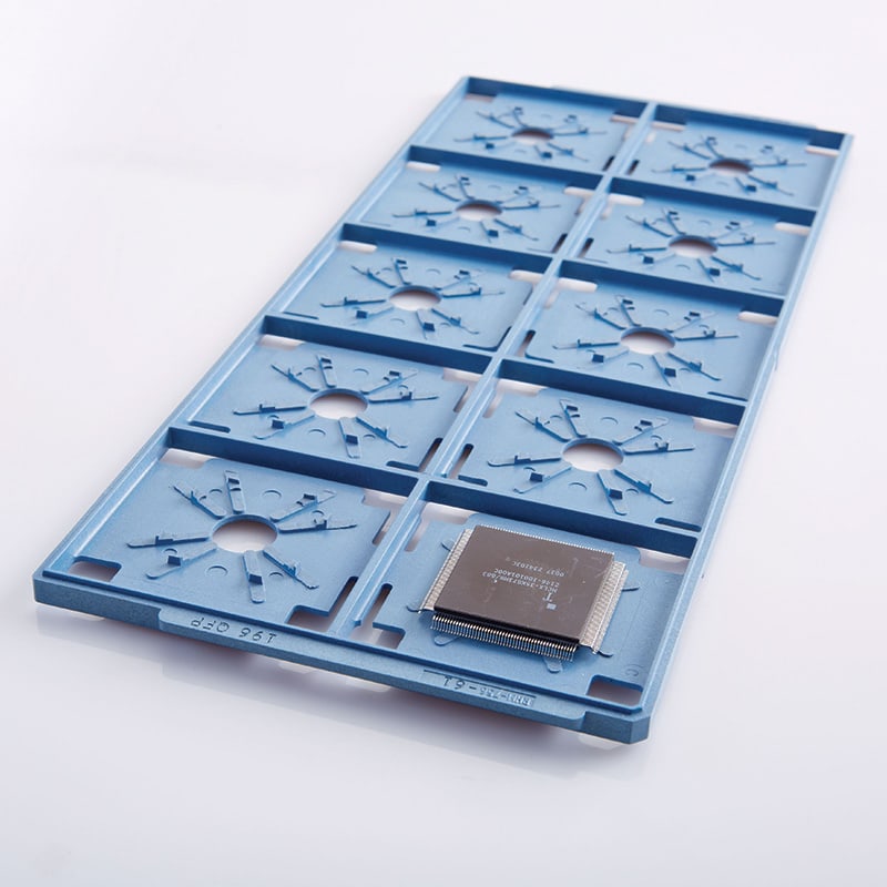
What Determines the Correct Tray Fit
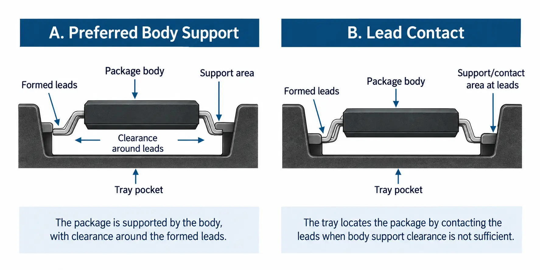
When possible, a QFP matrix tray is designed to hold the package body and not contact the leads. Typical data sheets give minimum, maximum, or loosely toleranced dimensions. Tray pockets must be correct and accurate to hold the devices while protecting the leads from damage.
Where the leads exit from, or attach to, the package body is important because it affects how the tray can capture the part. Bottom-brazed leads on packages without a bottom-side heat slug or thick lid make it very difficult to support and locate the device in the tray without lead contact and possible damage. Top-brazed leads are sometimes the highest features on the device, contacting the tray stacked above during shipping and handling.
The lead form’s shoulder length creates the needed clearance for tray features that fit the body and the leads, securely locating the device in the tray.
We recommend using device dimensions that are known to be representative and accurate within ±0.13 mm/.005 in.
Information to Include With Your QFP Tray Request
- Device description
- Measured package dimensions
- Length, width, and total thickness/height of the body
- Length, width, and total height of the bottom side of the body, slug, or lid
- Lead form dimensions, including shoulder length, exit height, tip-to-tip, pitch, and stand-off
- Lead pitch and lead count, listed per side if they are not the same on all sides
- Special details, including sidewall angle or draft and expected sealing overflow such as glass or epoxy
- Maximum tray temperature exposure
- Estimated tray quantity, or the total number of parts for which trays are needed
- Sample, drawing, and/or CAD model
When Lead Contact May Be Required
Some QFPs, including many TQFPs, do not have enough clearance between the leads and the body to allow JEDEC matrix trays to hold the parts in the preferred way without contacting the leads.
The trays for these parts will locate the parts by the leads. For these applications, confirm that lead contact for location in the tray will be acceptable.
Thin packages with short, stiff leads are often able to tolerate lead contact with the tray. Fine-pitch packages, devices with long, thin leads, and large, heavy devices are at most risk of damage.
Request a QFP JEDEC Matrix Tray
Accurate package and lead measurements will help determine how the device should be captured and supported in the tray.
Need a JEDEC matrix tray for a QFP package? Send us the information from the checklist above, along with a sample, drawing, and/or CAD model.