How to Get a JEDEC BGA Matrix Tray
Selecting the correct JEDEC matrix tray requires more than a BGA package description, ball count, or set of data sheet dimensions. This guide explains the information needed to evaluate a BGA, PBGA, TBGA, or other ball grid array package for the correct tray.
Finding the Right Information for Your Use
Ball Grid Array, BGA packages are a family of semiconductor devices, packages, and modules that use spherical solder balls for connection to PCBs, interposers, and other forms of interconnect.
BGAs are often described by either their total ball count, such as a 256 BGA, or their body dimensions, such as a 17 mm CBGA or 10 mm x 14 mm BGA.
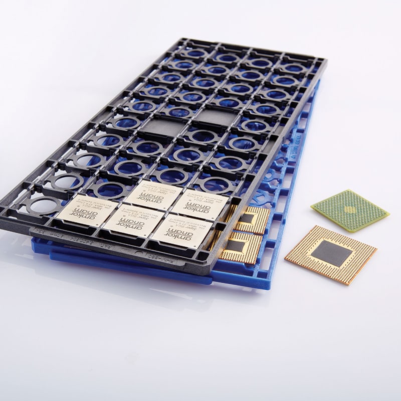
What Determines the Correct Tray Fit
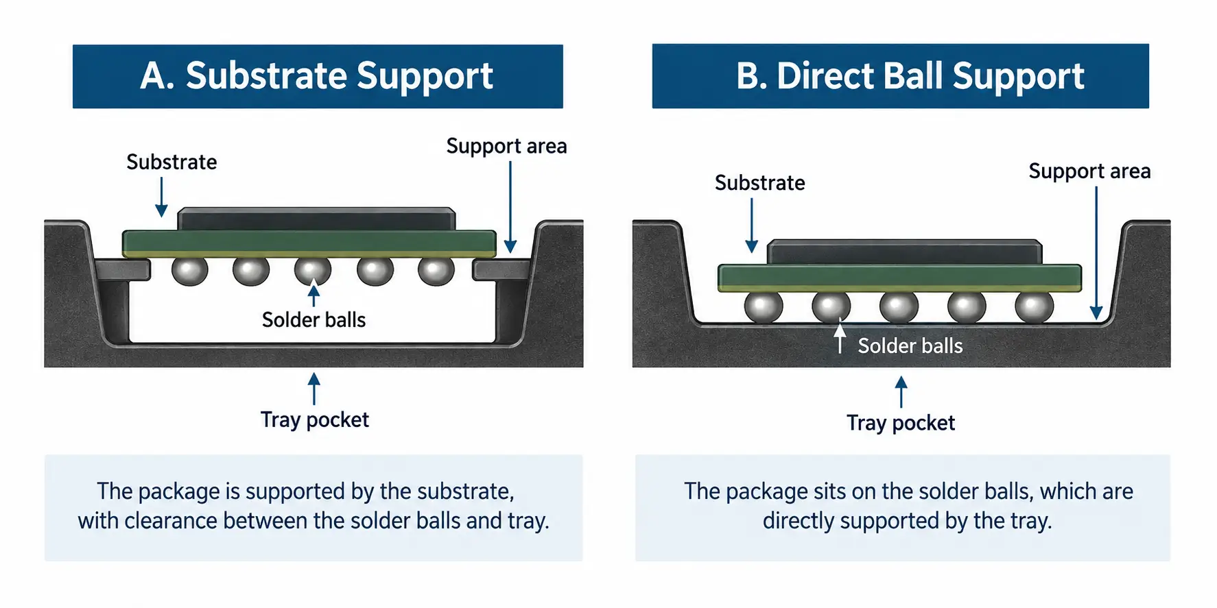
When possible, a BGA matrix tray is designed to hold the package body, support and locate the device by the substrate, and not contact the solder balls. Typical data sheets give minimum, maximum, or loosely toleranced dimensions. Tray pockets must be correct and accurate to hold the devices while protecting the balls from damage.
The substrate design, the size of the solder ball pattern, and the location of the pattern relative to the edge of the package determine the best way the BGA can be captured and supported in a tray. This impacts the tray design.
We recommend using device dimensions that are known to be representative and accurate within ±0.13 mm/.005 in.
Information to Include With Your BGA Tray Request
- Device description
- Measured package dimensions, including length, width, and total thickness/height
- Solder ball pattern size, location relative to the substrate edges, and population
- Solder ball size
- Maximum tray temperature exposure
- Estimated tray quantity, or the total number of parts for which trays are needed
- Sample, drawing, and/or CAD model
When the Ball Pattern Is Close to the Edge
When a BGA device has its ball pattern running close to the substrate perimeter, the small overhang and tolerances may leave too little clearance to support the device without risking side contact with the solder balls and/or falling off the support features.
Instead of trying to support the device with a very small step and risking contact with the balls from the side, it is often better to design the tray so the device sits with the balls directly on the tray. This applies only light compressive forces to the solder balls. The weight is distributed among many balls, and no side forces are applied.
Request a BGA JEDEC Matrix Tray
Accurate package measurements and solder ball information will help determine how the device should be supported in the tray.
Need a JEDEC matrix tray for a BGA package? Send us the information from the checklist above, along with a sample, drawing, and/or CAD model.